RECENT PROGRESS WITH
THE UNSW VANADIUM BATTERY
BY
MARIA SKYLLAS-KAZACOS
SCHOOL OF CHEMICAL ENGINEERING AND INDUSTRIAL CHEMISTRY
UNIVERSITY OF NEW SOUTH WALES, SYDNEY, 2052
INTRODUCTION
With increasing public awareness of issues such as global warming and declining
urban air quality, community pressure on governments and industry to clean up
the environment will see the inevitable shift away from the traditional fossil
fuels to renewable energy. Unfortunately, however for any new technology to gain
acceptance it must not only compete technically and environmentally, but also
economically with existing systems.
Recent research and development in the areas of wind and solar energy has led to
dramatic cost reductions which will allow these technologies to compete with
traditional electricity generation in the not too distant future. Already in
Australia, electricity generators are paying a premium price for so called
"green" energy, giving consumers the opportunity to support the
gradual introduction of renewable energy into the existing electricity grid
system. While a modest level of solar energy could be accommodated in the
electricity grid, however, the mismatch between the peak energy demand and solar
energy supply in different regions at various times of the year, means that an
efficient energy storage system would be required to capture and store high
levels of solar energy for domestic and industrial use.
The most efficient method for storing electrical energy is with electrochemical
cells or batteries. Although a number of secondary batteries have been under
development for many years, only the lead-acid and nickel-cadmium batteries have
to date achieved widespread commercial application. More recently the lithium
and nickel metal hydride batteries have emerged as excellent high energy density
alternatives, however, their current high cost has to date limited their use to
relatively small-scale portable equipment applications.
For a battery system to be economically viable for large-scale energy storage,
it must compete favourably with pumped water storage. Of all the new battery
technologies currently under development around the world, the redox flow cell
appears to offer the greatest promise as a low-cost, high efficiency system for
large-scale energy storage.
The vanadium redox battery being developed since 1984 in the School of Chemical
Engineering and Industrial Chemistry at the University of New South Wales
possesses many features which make it ideal for a large number of applications,
including solar energy storage, emergency back-up and load-levelling. The UNSW
vanadium redox battery, which falls into the general class of redox flow
batteries, employs solutions to store energy (1-5).
The use of solutions to store the energy overcomes many of the life limiting
problems associated with conventional batteries. Redox batteries can thus be
fully discharged without harm, they can be stored indefinitely at any
state-of-charge with only negligible self-discharge or irreversible capacity
loss, and there are no problems associated with shedding of active material, nor
short circuiting of the electrodes due to metal penetration of the separator.
FEATURES OF THE UNSW VANADIUM REDOX FLOW BATTERY
As illustrated in Figure 1, the Vanadium Redox Flow Battery employs the V(III)/V(II)
and V(V)/V(IV) redox couples in sulphuric acid as the negative and positive
half-cell electrolytes respectively.

Figure 1: Schematic of UNSW Vanadium Redox Flow Battery
The vanadium battery thus uses tanks to store two electrolyte "fuels"
which are pumped through a battery stack (power module) where the chemical
energy stored in the solutions is converted to electrical energy. The system is
analogous to an engine and fuel tank and provides great design flexibility by
separating the power source (battery stack) from the energy source (electrolyte
tanks).
In the vanadium redox cell, the following half-cell reactions are involved:
At the negative electrode:
V3+ + e- =====> V2+ E° = -0.26 V
At the positive electrode:
VO2+ + 2H+ + e- ======> VO2+
+ H2O E° = 1.00V
This gives a standard cell potential E° (cell) = 1.26 Volts at concentrations
of 1 mole per litre and at 25°C. Under actual cell conditions, an open-circuit
cell voltage of 1.4 Volts is observed at 50% state-of-charge, while a fully
charged cell produces over 1.6 Volts at open-circuit. The electrolyte for the
vanadium battery is 2 M vanadium sulphate in 2.5 M H2SO4,
the vanadium sulphate (initially 1 M V (III) + 1 M V (IV)) being prepared by
chemical reduction or electrolytic dissolution of V2O5
powder. The basic components of the redox cell are illustrated in Figure 2.
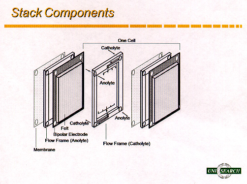
Figure 2: Components of the Redox Cell
The actual voltage needed to charge the battery and the voltage produced during
discharge when a load is connected, depend on the magnitude of the energy losses
associated with the internal resistance of the cell (R), the overvoltage losses
due to the kinetics of the system (activation overvoltage, na) and
the mass transport limitations (concentration overvoltage, nc):
Ecell = Ecathode - Eanode - iR - na
- nc
To maximise the cell voltage efficiency, therefore it is essential to minimise
the voltage losses during charging and discharging. The ohmic losses (iR) can be
minimised by selecting low resistivity membranes, electrode materials and other
cell components. The concentration overvoltage can be reduced with suitable cell
design to ensure good mass transport in the cell (i.e. high flow rate, uniform
electrolyte distribution).
The activation overvoltage depends on both the nature of the redox couple
reactions and the activity of the electrode material. The electrode material
used must also possess good stability during charging, good electrocatalytic
properties for the vanadium reactions and poor kinetics for hydrogen and oxygen
evolution so as to minimise gassing during charge. The relatively fast kinetics
of the vanadium redox couples allow high coulombic and voltage efficiencies to
be achieved without the use of expensive catalysts. The porous graphite felt
which is employed as the flow-through electrode, allows excellent mass-transfer
and permits greater surface area for the oxidation and reduction reactions.
The separator or membrane must be permeable to the charge balancing ions of the
supporting electrolyte, but prevent diffusion of the active species in solution
which would result in self-discharge of the battery. The ideal membrane should
thus exhibit low permeation rates of the active species to minimise
self-discharge and allow high coulombic efficiencies to be achieved. It should
also have a low resistivity to minimise losses in voltage efficiency, and it
should exhibit chemical stability for long cycle life.
The voltage of the battery is determined by the number of cells that are
connected electrically in series (using bipolar electrodes) in the cell stack.
The current on the other hand, is determined by the electrode area. The size of
the cell stack thus determines the output power of the system. The energy
storage capacity, however, is a function of the electrolyte volume.
For a vanadium concentration of 2 M, the energy density of the vanadium battery
is approximately 25 Wh/kg, this being acceptable for stationary applications.
Typically 30 litres of electrolyte (total volume) is needed per kWh of energy
storage. At higher vanadium concentrations, the required electrolyte volume can
be reduced, making the system more attractive for electric vehicles.
PROTOTYPE DEVELOPMENT AND FIELD TESTING
After selecting the most suitable electrode and membrane materials for
small-scale cell test results, their performance in larger prototype batteries
has been evaluated under continuous long-term cycling over a wide range of
operating conditions..The vanadium battery is now at a relatively advanced stage
of development with several 1-3 kW prototype batteries already constructed and
tested at UNSW. Overall energy efficiencies as high as 90% have been achieved
with early prototypes, not including pumping energy losses (3). These have been
estimated at 2-3%, so that even at 87-88% overall energy efficiency, the
vanadium battery is proving to be one of the most efficient energy storage
systems currently under development.
Since 1993 a number of field trials of the vanadium battery have been undertaken
both by UNSW and the University's licensees in Thailand and Japan. Details of
these trials are presented below:
(a) Vanadium Battery Solar House Trail in Thailand
In collaboration with UNSW Centre for Photovoltaic Device and Systems and
licensee Thai Gypsum Products Ltd, a vanadium battery storage system was
installed by the UNSW Vanadium Battery Group in a demonstration Solar House in
Thailand (6).
The solar energy system included 2.2 kW of installed solar cells and a 1 kW/12
kWh vanadium battery. The demonstration Solar House and installed vanadium
battery are shown in Figures 3 and 4 respectively. The original battery had 12
cells giving a system voltage of 16.8 volts and used 200 litres of each ½ -cell
electrolyte in the two reservoirs.
A 48 volt, 36 cell stack was later constructed in the laboratory and tested with
a 4 kW inverter and specially designed battery controller, prior to installation
in the demonstration Solar House in Thailand. The 48 volt battery replaced the
original 12-cell stack for long-term field trials.
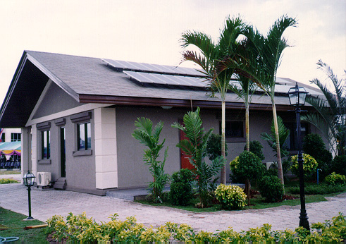
Figure 3: Photograph of demonstration Solar House in Thailand
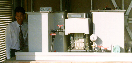
Figure 4: 1 kW/12 kWh Prototype Vanadium Battery Installed in Thailand Solar
House
The microprocessor controller built by the UNSW Centre for Photovoltaic Systems
and Devices, was designed to optimise the efficiency of the battery for this
application. One of the principal functions is to turn the pumps off during
periods of low charge or discharge rates so as to mimimise the pumping energy
losses in the system. Even with the pumps off approximately 1 kWh of energy is
stored in the battery stack itself. When the energy level of the stack
electrolytes reaches a preset threshold (as indicated by the stack voltage), the
pumps are turned on for 3-4 minutes so as to flush the stack with fresh
electrolytes before being turned off again. When the charging or discharging
current exceeds 20 Amps, however, the pumps operate continuously.
Another important feature of the vanadium battery is the fact that there is
negligible hydrogen evolution during charging and so there is no need for forced
ventilation. The battery room (Figure 4) is designed, however, to provide
natural ventilation (it is important to avoid high ambient temperatures) and
easy access for installation and maintenance.
One of the maintenance procedures which is used to rebalance the electrolytes
and restore the battery's full capacity, involves the periodic remixing of the
two solutions through a bypass line which connects the two tanks. This
rebalances the vanadium concentrations in the two half-cells, producing a
solution containing 50% V(III) and 50% V(IV) ions. On recharging the 2
solutions, the system's full capacity can be restored.
Depending on the system operation and type of membrane used, the remixing could
be required every 3-4 months.
Thai Gypsum is currently developing appropriate production methods for the
manufacture of electrodes and other battery components and is also evaluating
the feasibility of using vanadium batteries as peak shaving and emergency back
up systems in office buildings in Thailand.
(b) 200 kW/800 kWh Loading-Levelling Vanadium Demonstration Battery in Japan
In 1993, a consortium comprising Mitsubishi Chemicals and Kashima-Kita Power
Corporation of Japan licensed the UNSW vanadium battery technology for
stationary uses and has since spent several million dollars each year to scale
up the technology for large-scale load-levelling and solar energy storage
applications.
Kashima-Kita Electric Power Corporation employs vanadium rich Venezualan pitch
as the fuel for electricity generation, thus producing a high vanadium content
fly-ash as a waste product. An efficient chemical process was developed to
extract the vanadium from the fly-ash which is then used to produce a low-cost
vanadium electrolyte for the vanadium redox flow battery. A 3m3/day electrolyte
production plant was commissioned in early 1996.
In 1997, a 200 kW/800 kWh grid-connected vanadium battery was commissioned at
the Kashima-Kita Electric Power station in Japan where it is currently
undergoing long-term testing as a load-levelling system. By the beginning of
1998, it had already undergone 150 charge-discharge cycles and was continuing to
show high energy efficiencies of close to 80% at current densities of 80-100 mA/cm2.
The specifications of the 200 kW/800 kWh battery are as follows:
Number of stack modules = 8 x 25 kW stacks
Stack configuration = 3 substacks per stack (21 cells per substack)
Electrode area = 4000 cm2
Electrolyte volume = 23 m3
Electrolyte vanadium concentration = 1.8 mol/l
System voltage = 500 V
Charge and discharge current = 400 Amps
The 200 kW vanadium battery stack modules are shown in Figure 5.
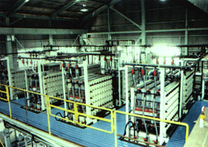
Figure 5: 200 kW Vanadium Battery Modules at Kashima-Kita Power Plant in Japan
As in the case of solar energy storage, the important features of the vanadium
battery for this application are:
· Low cost for large storage capacities. Cost per kWh decreases as energy
storage capacity increases, typical projected battery costs for 8 or more hours
of storage being as low as US$150 per kWh.
· Existing systems can be readily upgraded and additional storage capacity can
be easily installed by changing the tanks and volumes of electrolyte.
· High energy efficiency.
· Capacity and state-of-charge of the system can be easily monitored by
employing an open-circuit cell.
· Easy maintenance.
· Flexibility.
(a) UNSW Emergency Back-Up Battery for Submarine Applications
A VRB emergency back-up battery was recently designed and built at UNSW to meet
the desired operating conditions specified by the Department of Defence (7). Its
intent was to allow a comparison with the current nickel/cadmium system employed
as a back-up battery in submarines. The primary requirements for the VRB Defence
system were that it should be charged between 5% and 95% of its rated capacity
while remaining in the voltage range of 22 V to 28 V under loads of 0 to 160 A.
The capacity of the current nickel/cadmium system was 160 Ahr, therefore, the
VRB Defence battery was designed to meet and preferably exceed this capacity,
even at high constant loads.
Unlike other battery systems the charge and discharge voltage of the vanadium
battery stack can be chosen by introducing tapped cells. This provides the
opportunity to change the operating conditions so as to protect sensitive
equipment from large voltage fluctuations and allow operation within a narrow
voltage window for charging and discharging.
The vanadium redox battery emergency back-up system shown in Figure 6, comprises
of two battery stacks electrically connected in parallel, each containing 19
cells with a tapping cell placed at cell No. 17 in each stack. The battery is
thus charged across 17 cells and discharged across 19 cells, thus allowing an
overall voltage window of 22 to 28 volts to be maintained during charge and
discharge.

Figure 6: Vanadium Redox Battery Defence Emergency Back-Up System.
The battery was charged and discharged at a range of currents ranging from 40 to
120 Amps and high overall energy efficiencies of 77 to 81% were obtained, even
with the high charging currents.
The theoretical maximum capacity of the system based on 19 cells and 83 litres
of 1.8 M vanadium solution per half-cell series, is calculated as 210.8 Ahr.
Discharging the battery across 19 cells from a fully charged state to a lower
voltage limit of 22 V, produced 183 to 162 Amphours over the discharge current
range of 60 to 120 Amps.
This represents an utilisation of between 77 and 87% of the theoretical
capacity, which again is an excellent result.
(b) UNSW Vanadium Battery Powered Electric Golf Cart
One of the unique features of the vanadium battery which makes it highly
attractive for mobile application is its ability to be both electrically
recharged and mechanically recharged by exchanging electrolytes.
Although there are a number of high profile battery technologies under
development, these currently suffer from an anticipated high whole of life cost
together with various functional limitations including slowness in recharging
and cooling.
In contrast to these essentially complex batteries, the vanadium redox flow
battery is an inherently simple battery with potential for low manufacturing
cost and demonstrated indifference to deep cycling and very high charge and
discharge rates.
In order to demonstrate the vanadium battery in a mobile application, therefore,
a 36 volt vanadium battery prototype was installed in a commercially available
electric golf cart at UNSW in 1994 where it was subjected to over 2 ½ years of
off-road testing (8). The photograph in Figure 7 shows the vanadium battery
powered golf cart with the 5 kW battery stack mounted on the back and
electrolyte tanks under the seat. This 5 kW stack is considerably oversized for
this application and with suitable re-engineering a compact stack of one-quarter
of the present size should be achievable.

Figure 7: UNSW Vanadium Battery Powered Electric Golf Cart
To achieve a compact stack design, thinner flow-frame dimensions (3 mm compared
with original 5 mm) were employed in a second prototype stack which was
installed in the golf cart in early 1997.
Extensive off-road trials of this battery showed excellent performance over a
range of terrains. With 40 litres of 1.85 M vanadium electrolyte per half-cell
tank, a driving range of 17 km was obtained. The total driving range expected
for 3 molar vanadium solutions and full tanks containing 60 litres each side,
therefore, is around 40 km.
A new improved 3 M vanadium solution has been undergoing bench-testing since
late 1997 and is currently being evaluated in the golf-cart battery. Preliminary
results look very promising and if long-term testing prove to be successful, a
practical 3 molar vanadium electrolyte with energy density of over 35 Wh/kg will
be available for commercial application. Further research into air regeneration
of the positive electrolyte, should double this to over 70 kW/kg (9).
While the present energy density is relatively low compared with new high energy
density systems like the lithium, nickel-metal hydride and sodium nickel
chloride batteries, a practical driving range of around 120 km would still be
expected in an electric vehicle applications. In particular, the use of vanadium
batteries in electric buses would allow 24 hour a day use of the buses if
electrolyte refueling is employed every 4-5 hours during driver rest breaks as
illustrated in Figure 8.
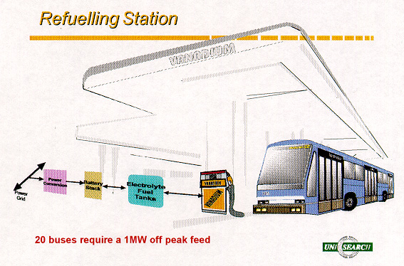
Figure 8: Vanadium Battery Refueling Station Concept for Electric Buses.
CONCLUSIONS
Several demonstration projects at both UNSW and overseas have shown the
technical viability of the vanadium battery for a wide range of stationary and
mobile applications.
The vanadium battery is at an early stage of its productionisation and
manufacturing life cycle and it is expected that manufacturing costs will be
reduced rapidly with improved materials, more advanced mechanical design,
process improvements and volume manufacturing economies.
Cost estimates by the UNSW group and independent consulting groups (10, 11),
place mass production costs at between $100 and $300 per kW for the stack and
$30 to $50 per kWh for the electrolyte.
In addition to the low projected manufacturing costs, other attractive features
of the vanadium battery include:
· Ability to accept rapid charging/discharging rates.
· Potential for long life and consequent low whole of life costs.
· Five minute recharging by electrolyte replacement.
· Self-cooling (of special importance in large dense battery stacks).
· Positive environment impact.
When combined with newly increased energy (12) and power density the vanadium
battery is one of only a few battery technologies which hold realistic promise
for large-scale energy storage in the near term and for successfully powering
production electric vehicles beyond 2000.
In September 1998 all patents, technology, know how and licenses associated with
the vanadium battery were bought by an Australian company, PinnacleVRB, who plan
to commercialise the technology for stationary and mobile applications.
REFERENCES
(1) M. Skyllas-Kazacos and R G Robins, "The All Vanadium Redox
Battery", US Patent No. 849, 094 (1986).
(2) M Kazacos and M Skyllas-Kazacos, "Performance Characteristics of Carbon
Plastic Electrodes in Vanadium Redox Cell", J Electrochem. Soc. 136, 2759
(1989).
(3) M Skyllas-Kazacos, D Kasherman, D R Hong and M Kazacos,
"Characteristics and Performance of 1 kW UNSW Vanadium Redox Battery",
J Power Sources, 35, 399-404 (1991).
(4) "Status of the UNSW Vanadium Redox Battery Development", M
Skyllas-Kazacos, in Proceedings 9th Australasian Electrochemical Conference,
Wollongong, February 1994, pp 033-1 to 033-4.
(5) "Conductive Carbon-Polypropylene Composite Electrodes for Vanadium
Redox Flow Battery", V Haddadi-Asl, M Kazacos and M Skyllas-Kazacos, J Appl
Electrochem., 25, 29-33 (1995).
(6) R Largent, M Skyllas-Kazacos and J Chieng, "Improved PV System
Performance using Vanadium Batteries", Proceedings IEEE 23rd Photovoltaic
Specialists Conference, Louisville, Kentucky, May 1993.
(7) "Vanadium Back up Battery for Submarine Application", C Menictas,
D R Hong, M Kazacos and M Skyllas-Kazacos, Final Report, Australian Defence
Dept., Oct., 1995, pp120.
(8) "Status of the Vanadium Redox Battery Development Program", C
Menictas, D R Hong, Z H Yan, J Wilson, M Kazacos and M Skyllas-Kazacos,
Proceedings Electrical Engineering Congress 1994, Sydney, NSW, November 1994.
(9) "Vanadium/Oxygen Redox Fuel Cell" by C Menictas and M
Skyllas-Kazacos, Final Report to NSW Office of Energy, State Energey Research
and Development Fund, April 1997.
(10) "Commissioned Study into the Prospects for Using Energy Storage in
Australia", Report to Dept of Primary Industries and Energy by McLennan
Magasanik Associates Pty Ltd, January 1990.
(11) "Viability Assessment of Vanadium Redox , Battery Manufacturing in
Australia", Report to Energy Research Development Corporation by Strategic
Industry Research Foundation, April 1995.
(12) "High Energy Density Vanadium Electrolyte Solutions for all-Vanadium
Redox Battery" M Skyllas-Kazacos and M Kazacos, International Patent
Application No. PCT/AU96/00268, May 1996.


