Uses vanadium solution in bath half-cells
Same solution pumped through each cell in stack
After selecting the most suitable electrode and membrane materials from small-scale cell test results, their performance in larger prototype batteries has been evaluated under continuous long-term cycling over a wide range of operating conditions.

Fig 1. Schematic of UNSW Vanadium Redox Battery[7].

Fig 2. Components of the Redox Cell[7].
The vanadium battery is now at a relatively advanced stage of development with several 1-3 kW prototype batteries already constructed and tested both as emergency back-up batteries and in an electric golf-cart at UNSW. Overall energy efficiencies as high as 90% have been achieved to date, not including shunt current and pumping energy losses. These have been estimated at 2-3%, so that even at 87-88% overall energy efficiency, the vanadium battery is proving to be one of the most efficient energy storage systems currently under development.
In addition to the technical benefits described in Table 1, other features include:
Redox cell batteries[8] are thus the only type of battery systems which offer the possibility of efficient “instant recharge”. Although the aluminium/air and zinc slurry/air systems allow mechanical recharge, in both cases the recycling of the active materials is much more complicated and energy inefficient (e.g. the Hall-Heroult process for producing metallic aluminium has less than 50% energy efficiency). Unlike other batteries therefore, the vanadium battery can be both electrically recharged and mechanically recharged.
3. Advantages of Vanadium Redox Battery for Emergency Back-Up Applications
Many UPS systems employ lead-acid batteries with or without a diesel generator. Due to the poor performance and short cycle life of the lead-acid battery under deep discharge cycling, there is a heavy dependence on the diesel generator for longer term power generation in the event of power failure. With a low cost, efficient battery, however, considerable reduction or complete replacement of the diesel generator could be possible in the near future.
The important features of the vanadium battery for this application are:
4. Performance of Vanadium Redox Battery in Emergency Back-Up System
A VRB emergency back-up battery was recently designed and built to meet the desired operating conditions specified by the Department of Defence. Its intent was to allow a comparison with the current nickel/cadmium system employed as a back-up battery. The primary requirements for the VRB Defence system were that it should be charged between 5% and 95% of its rated capacity while remaining in the voltage range of 22 V to 28 V under loads of 0 to 160 A. The capacity of the current nickel/cadmium system was 160 Ahr, therefore, the VRB Defence battery was designed to meet and preferably exceed this capacity, even at high constant loads.
The vanadium redox battery defence system shown in Figure 3, comprises of 2 battery stacks each containing 19 cells with a tapping cell placed at cell No.17 in each stack.

Fig 3. Vanadium Redox Battery Defence Emergency Back-Up System.
The system also uses a small external cell which gives the open-circuit voltage between the positive and negative electrolytes. The electrolyte storage tanks are made from impact resistant plastic and the volume of electrolyte employed is 83 L per half-cell series. The two tanks share a common wall to separate them. An anti-syphoning balance pipe is incorporated in the tanks to allow any solution passing the fill limit of one tank to flow back into its place of origin in the adjacent tank. This allows over design to be minimised, while ensuring that a high safety and reliability level is maintained in the system's components.
The design of the VRB Defence battery required 2 stacks comprising of 19 cells each to be electrically connected in parallel. Each stack contains a tapping cell at cell no.17 which also must be taken into consideration when the electrical connection is made.
Battery Stack 1 contains conducting plastic electrodes and unactivated graphite felt. The membrane used in this battery is Selemion AMV membrane (Asahi Glass, Japan). The battery was connected to all the system components in order to make a functioning VRB battery system employing only one stack. This battery was then tested at various currents to determine its performance. Table 2 summarises the efficiencies obtained at various constant charge/discharge currents.
The efficiencies shown in Table 2 were not as high as expected and this is mainly due to the lower than expected voltage efficiencies due to the use of unactivated felt and the AMV membrane.
Table 2 Efficiencies for Stack 1 at various constant charge/discharge currents.
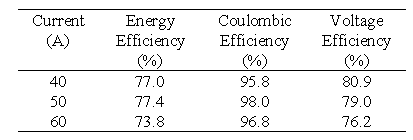
The average cell resistance was calculated by carrying out a polarisation test on the battery. The battery is first charged to a 50% state of charge (SOC) before the test is carried out. Once this level is reached the battery is charged and discharged for 1 min time intervals at different currents as shown in Table 3.
Table 3 Polarisation test results for Stack 1 performed at a stack open-circuit voltage of 25.8V at approximately 50% state of charge.
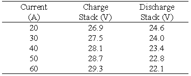
From the slope of the voltage versus current curves the average cell area resistivities during charging and discharging were calculated as 4.74 ohms cm2 and 4.89 ohms cm2 respectively. From the cell resistivities it is evident that the low voltage efficiencies obtained are the result of a higher than expected average cell resistivity. The major physical contributors to the cell resistivity are the electrodes and membranes. In this particular battery the majority of electrode resistivities are between 0.7 - 1.3 ohms cm2 and the Selemion AMV membrane has a resistivity rating between 1.5 - 3.0 ohms cm2. This resistivity can vary in production batches therefore a major contributor to the cell resistivity obtained is the membrane. With constant cycling, battery efficiency improves however, the measurement of cell area resistivity early in the battery's life establishes an area resistivity value that is not significantly influenced by battery cycle history.
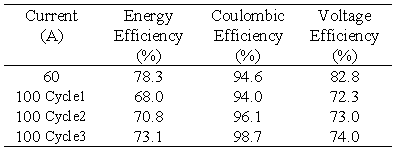
The second battery stack in the VRB Defence project employed a second type of conducting plastic electrode and graphite felt. A tapping cell is incorporated at cell no.17 and the membrane employed was the experimental New Selemion Type II membrane (Asahi Glass, Japan) which has an area resistivity in the vicinity of 1 cm2. This battery stack was connected to the rest of the vanadium battery system. The stack was then tested at various constant charge/discharge currents with the efficiencies obtained presented in Table 4.
The energy efficiency obtained with this battery at 60 A is markedly higher than with Stack 1 ie. 78.3 compared with 73.8%. As the battery becomes conditioned, however the efficiency is seen to improve. Three 100 A cycles were carried out continuously, to test the behaviour of the battery. It is important to observe, that with each cycle the coulombic efficiency, the voltage efficiency, and the energy efficiency all increase steadily.
Table 4 Efficiencies for Stack 2 at various constant charge/discharge currents.
A polarisation test was performed on Stack 2 to ascertain the average cell resistance in the battery with the polarisation test results shown in Table 5.
Table 5 Polarisation test results for Stack 2 performed at a stack open-circuit voltage of 26.3V at approximately 50% state of charge.
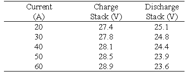
The average cell area resistivities calculated from the data in Table 5 were 2.90 ohms cm2 for charging and 3.13 ohms cm2 for discharging. These area resistivities obtained are significantly lower than for stack 1 due to the use of the lower resistance New Selemion membrane. As such, the battery possesses higher overall energy efficiencies which are expected to improve with further cycling of the battery.
Two-Stack Battery Performance Analysis The performance of the VRB Defence battery system was tested under 2 main operating modes. The first involved utilisation of all cells in the battery system. This was required for the determination of overall efficiencies, resistance measurements and self-discharge tests. The second mode utilised the tapping cells, for example charging the battery system across 17 cells and discharging the battery system across 19 cells. This mode was used in tests that required the battery voltage to be maintained within specified voltage limits.
The efficiency of the battery system was investigated in a current range of 40 - 120 A with the upper current of 120 A being the maximum deliverable current from the power supply. Table 6 below summarises the efficiencies obtained at each current. In this test series the charge and discharge currents were constant at each respective current and for the duration of each test cycle.
Table 6 Total battery efficiencies at various constant charge/discharge currents.
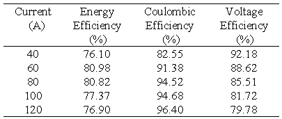
The results presented in Table 6 are also plotted in Figure 4. Figure 4 shows that as expected, coulombic efficiency increases and voltage efficiency decreases with increasing current giving a maximum overall energy efficiency of over 80% in the current range of 60-80 amps.

Fig. 4 Total battery efficiency profiles.
A typical voltage profile for the stack voltage during charging and discharging at 100 A and the corresponding OCV stack voltage profile is illustrated in Figure 5. The OCV profile of Figure 5 shows the stack voltage for zero current flow and thus represents the ideal voltage path with zero losses. The actual stack voltage, however, contains deviations from ideality due to the resistance and polarisation losses in the battery. A higher voltage is thus needed during the charging phase and a lower voltage is available during the discharge phase. It is therefore important that the resistance of the battery system be minimised, to allow maximum utilisation of the available energy.
The internal resistances of the individual batteries were calculated as described above and a polarisation test was also carried out to determine the resultant overall resistance for the 2 stack battery which is both hydraulically and electrically connected. The resulting polarisation plot is illustrated in Figure 6.

Fig. 5 Total battery voltage and open-circuit voltage profiles at a constant charge/discharge current of 100 Amps.

Fig. 6 Polarisation plot for the total battery system.
The average cell resistivities of the total battery system at 50% SOC for the charge and discharge cycles were calculated as 3.66 ohms cm2 and 3.84 ohms cm2 respectively. These values compare favourably to the theoretical values of 3.60 ohms cm2 for the charge cycle and 3.82 ohms cm2 for the discharge cycle, calculated for a parallel system from the individual stack resistivities previously measured.
Tapping Cell Utilisation
The tapping cells are cells that allow current to be transferred into or out of the battery in addition to the 2 end electrodes. The tapping cells were a bipolar arrangement employing an internal copper current collector to allow the exchange of high currents. One tapping cell was incorporated into each stack at cell no.17. The tapping cells were also connected in the parallel network, therefore the total battery system could be charged or discharged across 17 or 19 cells. The main design purpose of the tapping cells was to allow charging across 17 cells and discharging across 19 cells thus limiting the difference between the charge and discharge voltages.
The testing of the tapping cells involved charging the battery across 17 cells at high constant currents, while ensuring that the total battery stack voltage did not exceed 28 V. The battery was then discharged across 19 cells until the total battery stack voltage reached 22 V.
A typical voltage profile for the 17 cells charge - 19 cells discharge, 100 A constant current cycle is illustrated in Figure 7. The upper and lower voltage limits are also shown in the figure, highlighting the voltage limits between which the battery was cycled.

Fig. 7 Voltage profile for charge/discharge across 17/19 cells at 100A.
One of the main characteristics of this cycling which is immediately noticeable, is the difference in length ie. time for the charge and discharge profiles. While this would suggest a low coulombic efficiency, it is important to keep in mind that during the charge cycle only 17 cells are employed to charge the battery, therefore, a lower voltage is imposed. Cells 18 and 19 in each stack are at open circuit during charging, thus the charge time utilising 17 cells will obviously be longer than when all 19 cells are used. Similarly, it is expected that the Ahr out will be less when discharging across 19 cells than if discharging 17 cells. However, the voltage will be higher and within the prescribed voltage limits. Rather than evaluating the coulombic efficiency of this battery therefore, the best indicator of its performance is the overall energy efficiency which in this case was up to 79%.
The results obtained at the four different currents are presented in Table 7.
Table 7 shows that at constant discharge currents below 100 A the system meets and exceeds the 160 Ahr capacity of the nickel/cadmium system presently employed as the back-up battery. It should be noted however, that in the VRB battery system the capacity figures given in Table 6 are not for a fully charged battery but for a battery that has been charged at a constant current until the 28 V upper limit has been reached. From Figure 7 and Table 7 it is seen that approximately 2 hours are needed to charge the battery up to 92.5 % capacity, at a constant current of 100 A. At 120 A it only takes 1.5 hours to charge the battery up to 90.5 % capacity while not exceeding the 28 V upper limit.
The advantage of this type of battery is immediately apparent in the charging time required to charge the system. Ideally, a power supply system that can handle higher currents would charge the battery in under 1 hour. It is important to note however, that a generator works on a constant voltage charging principle ie. as the voltage of the battery nears the upper voltage limit set in the generator the current tapers off to trickle charging. To gain the rapid charging benefits of the VRB system a constant current charging supply is recommended.
Maximum Capacity Utilising Taper Charging The full capacity of the system was demonstrated by discharging the battery from a fully charged state (taken as 98 %).
Table 7 Results obtained at different constant currents when utilising the tapping cells in the voltage limits of 22 V and 28 V.

* Theoretical maximum capacity = 210.8 A.hr Based on 19 cells and 83L of 1.8M vanadium solution / half-cell.
The total battery system was charged across 17 cells at 120 A. Once the battery was charged to the maximum SOC possible at this current, the charge current was lowered to 100 A. This method was continued until the final charging current reached 40 A. By this stage the battery had reached an SOC above 98 %, the total charging time being approximately 2 hours.
The results obtained for discharging the total battery system across 19 cells at different constant discharge currents to a lower stack voltage limit of 22 V, are summarised in Table 8 and Figure 8(a).

Fig. 8 Amp.hours.out versus discharge current for the total battery system discharged from 98% SOC to a lower voltage limit of 22V. Curve (a) for a cell resistance of 3.8 ohms cm2, (b) for a cell resistance of 2 ohms cm2.
The discharge profiles obtained are shown together in Figure 9.
At all of the currents shown in Table 8 the Ahrs out exceeded 160 Ahrs before the battery reached the 22 V limit. The Ahrs out is a direct consequence of how low the battery could be discharged. At 120 A the resistance of the battery is such that when the 22 V limit is reached the battery is only discharged to 19% SOC.
If the resistance of the battery is lower it can be discharged to a lower state before the 22 V limit. In fact, if a cell resistance of 2.0 ohms cm2 is assumed (which is now readily achievable with available materials), at the 22 V lower limit and 120 A discharge, the battery OCV would be 25.04 V, this corresponding to an SOC of 17 % at the end of discharge. Similarly, at 60 A an SOC of 4 % would be reached at the end of discharge corresponding to 90 % capacity utilisation assuming similar coulombic losses as in Table 7. The projected Amp.hours versus discharge current for a stack with a cell resistance of 2 ohms cm2 is given in Figure 8, Curve (b)

Fig. 9 Discharge voltage profiles for the fully charged battery system showing 22V and the total discharge 15.2V limit.
A float test was carried out for over 70 hours and in that time the total current required to keep the battery stack at the constant voltage of 26.6 V (50% SOC) was only 0.28 A.
VRB Employing Glassy Carbon Electrodes. A 19 cell battery stack was initially constructed employing glassy carbon electrodes. The glassy carbon material is extremely conductive and certain parts of the electrode needed to be insulated, due to the current design of the flow-frames used for construction of the VRB stacks. While a new flow-frame suitable for glassy carbon electrodes is currently being designed, this was not available for the Emergency Back-Up battery project.
Table 8 Results obtained when discharging the total battery system across 19 cells from a fully charged state to a battery lower voltage limit of 22 V.

* Theoretical maximum capacity = 210.78 A.hr Based on 19 cells and 83L of 1.8M vanadium solution / half-cell.
The glassy carbon battery system was charged across 19 cells at a current of 20 A. At 85% SOC the battery charging voltage at 20 A was 28.97 V. The voltage was also measured across 17 cells and found to be 25.89 V. The open-circuit stack voltage across 17 and 19 cells at 17% SOC was 22.42 V and 25.06 V respectively. This again highlights the different voltages that can be obtained at the same SOC when using the tapping cell.
The average cell resistivity calculated at 50% SOC during charging was 1.89 ohms cm2. This cell resistivity shows that low resistivities can be obtained with currently available materials.
5. Cost Projections
The four phases of the commercialisation plan over the first six years are:
Table 9 projects the effect of the cost cutting initiatives and shows a plan to reduce the cost of the cell stack components from $879 to $133 per kW.
By using economies of scale and process improvements the cost of electrolyte is expected to be reduced as shown in Table 9.
The costs in Table 9 and 10 do not include the auxiliary systems costs comprising of plumbing, pumps, tanks, power conversion equipment and battery controller.
An approximate comparison of the cost per installed kW of vanadium battery storage compared with lead acid battery for a range of hours storage is shown in Figure 10.

Fig. 10 Battery cost versus battery capacity.
Table 9 Cost ($/kW) of battery stack components based on a 100kW stack.
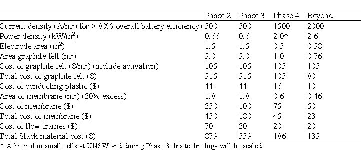
Table 10 Electrolyte Cost ($/kWh)

The total vanadium battery costs in $/kWh decrease with increasing storage time as shown in Figure 11.

Fig. 11 Total vanadium battery costs versus storage time.
6. Commercial Developments
To date, two commercial licenses have been granted by Unisearch Ltd for the commercialisation of the vanadium redox battery in stationary energy storage applications. Thai Gypsum Products (Thailand) have been granted a license to manufacture and use the vanadium redox battery in residential photovoltaic applications and non-grid interactive commercial peak-shaving systems in South-East Asia. A consortium comprising Mitsubishi Petrochemicals and Kashima Kita Power Corporation of Japan has also been licensed to further develop and commercialise the vanadium redox battery world-wide (excluding South-East Asia, China and Australia) in large-scale load-levelling systems. A 200kW/800kWh vanadium battery system was commissioned in Japan in 1997 and is currently undergoing grid-connected testing. A 2MW demonstration load-levelling system is to be commissioned in the Tokyo area by the end of 1999.
In May 1997, Unisearch Ltd granted an option for exclusive world-wide rights to the VRB technology for electric vehicle applications to the Australian Company Pinnacle Mining NL.
7. Conclusion
The design and evaluation of the vanadium emergency back-up battery system has confirmed that it has highly desirable characteristics for emergency back-up applications. It offers many advantages over conventional type battery systems which have restricted the design of efficient and reliable back-up power systems.
The ability of the vanadium battery to be both mechanically and electrically recharged provides added flexibility, as does the ability to accurately determine the state-of-charge and capacity of the battery directly from the open-circuit voltage of the electrolytes.
The vanadium battery system is a reliable and cost effective energy storage system which offers independent power and capacity ratings at high efficiencies. System design advances and energy density increases are continuing as the system approaches commercialisation.
8. References
[1] M. Skyllas-Kazacos and R. G. Robbins, “The All Vanadium Redox Battery”, U. S. Patent No. 849 094 (1986)
[2] E. Sum and M. Skyllas-Kazacos, Journal of Power Sources, 15 (1985) 179.
[3] E. Sum, M. Rychcik and M. Skyllas-Kazacos, Journal of Power Sources, 16 (1985) 85.
[4] C. Menictas, D.R. Hong, M. Kazacos and M. Skyllas-Kazacos, “Vanadium Battery Solar Demonstration House”, Proceedings of the Solar `94 Conference, Sydney, Australia, Vol 2 (1994) 611.
[5] C. Menictas, D. R. Hong, Z. H. Yan, J. Wilson, M. Kazacos and M. Skyllas-Kazacos, “Status of the Vanadium Redox Battery Development Program”, Proceedings of the Electrical Engineering Congress, Sydney, Australia, Vol 1 (1994) 299.
[6] C. Menictas, T. Tran and M. Skyllas-Kazacos, “The Dissolution of V2O5 in Vanadium Sulphate Solution”, Proceedings of the Ninth Australasian Electrochemistry Conference, Wollongong, Australia, Vol 2 (194) 66.
[7] The Vanadium Redox Battery Website, “www.ceic.unsw.edu.au/centers/vrb/webframe/ option1.htm”.(1996).
[8] M. Bartolozzi, Journal of Power Sources, 27 (1989) 219.