The rush to harness energy from the sun to make electricity has inevitably fueled the development of large industrial-grade grid-tie inverters (GTI) that convert DC from photovoltaic (PV) panels into AC power for commercial use. Compared to their residential forerunners that generated only a few kilowatts (kW) of power, the mammoth systems of today are designed to put out upwards of 100kW. While these super-sized powerhouses can dramatically lessen reliance on utility power, there is something else they do that may surprise you.
Customers with PV systems that have displaced a good portion of utility power and whose loads have a sizable reactive component can actually see utility power factor deteriorate after their system is connected to the grid. Low power factor presents a heavier generation and transmission burden on the power grid and also deposits a larger carbon footprint. Because of this, most tariffs have provisions allowing the utility to charge a penalty for low power factor. But it is possible to address this problem.
Background on commercial power
We begin with a basic discussion of the different kinds of commercial power. One is called real power because it is directly related with doing real and useful work such as heating and lighting. Resistive loads are consumers of real power, whose common unit of measure is the kilowatt (kW). In a resistive load, both supply voltage and load current are "in-phase" such that the peaks and troughs of their sinusoidal waveforms coincide and constructively work together.
Another kind of power is reactive power that is present in loads with inductive or capacitive elements in them such as motors and lamp ballasts. Unlike real power, reactive power behaves differently by storing energy in the electric and magnetic fields of the reactive load and releasing it back to the grid on each AC cycle, made possible because supply voltage and load current are 90-degrees out-of-phase with each other. The unit for reactive power is the kilo-volt-ampere reactive (kVar).
The relationship between real and reactive power is represented by the right triangle shown in Figure 1 where real power falls on the horizontal axis and reactive power rises on the vertical. The vector sum of real and reactive power is called apparent power, whose magnitude is the length of the hypotenuse and whose common unit of measure is the kilo-volt-ampere (kVA). Seen another way, apparent power is the total burden placed on the grid by the load from both its real and reactive parts.
 |
| Figure 1. Relationship between real, reactive and apparent power. |
In Fig. 1, the cosine of the angle φ (a fraction between 0 and 1) represents power factor at the fundamental power line frequency -- commonly known as displacement power factor associated with linear loads where a phase shift exists between supply voltage and load current. A lagging power factor is associated with an inductive load, while a leading one is indicative of a capacitive load.
Power factor can also be affected when harmonic components of the fundamental frequency are present in magnitude to distort the waveform of the load current. True power factor is then a combination of simple phase displacement and harmonic distortion. Because of the technical complexities associated with harmonic distortion, the remaining discussion will be focused solely on displacement power factor.
The power factor represents the degree to which the load is resistive with the ideal occurring when φ is zero degrees and power factor equals one, or unity. At unity power factor, apparent power equals real power, reactive power is zero and the load is purely resistive in nature. If the load also contains reactive elements (as most do), reactive power will be non-zero and apparent power will exceed real power as Fig. 1 shows. Therefore, given two loads each consuming the same amount of real power, the one with the higher power factor will be more efficient and draw less circulating current than the other with the lower power factor.
The inefficiencies associated with low power factor require larger power plants and bigger transmission lines to generate and deliver the higher currents. For this reason, the utility must set minimum power factor standards in accordance with applicable tariffs to mitigate the problem. Non-conforming users with sub-par power factor may be penalized with higher rates.
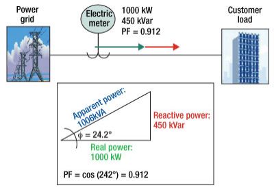 |
| Figure 2. Utility power factor without grid-tie inverter (GTI). |
Putting it all together
Having the basics covered, let's focus our attention on Figure 2, which shows an example of a commercial load connected to the grid through the electric meter. The meter shows that the load draws 1000kW of real and 450kVars of reactive power, which results in a respectable power factor of 0.91 as indicated by the triangle in Fig. 2.
In Figure 3, we have the same configuration except this time a large GTI unit displaces 50% of utility real power. In other words, the grid and GTI each feed 500kW to the load. The meter now registers 500kW of real power and the full 450kVars of reactive power as well. Crunching the numbers again, you find the power factor has dipped to 0.74. What caused this plunge of 19%, you may ask?
Remember that power factor can be decreased in a couple ways. One is by holding real power (kW) constant while increasing reactive power (kVars). The other way is to keep reactive power constant and trim real power, which is precisely what is happening here. The missing piece of the puzzle is the fact that GTIs are designed to operate with a unity power factor output and be synchronized with grid frequency. Recall that a system with unity power factor exhibits 100% real and 0% reactive power. So the GTI does not contribute any reactive kVar production to the equation, which leaves the utility to bear the entire burden. The reason for the mysterious drop in power factor now becomes clear.
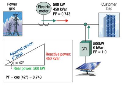 |
| Figure 3. Utility power factor with grid-tie inverter (GTI). |
What can be done to ensure that power factor falls within acceptable utility limits? In reality, PV power output is not constant but fluctuates throughout the day depending on the sun's position and cloud cover. Because of the inversely proportional relationship between PV output and utility power factor just explained, the latter will also fluctuate throughout the day. However, if average power factor falls below utility standards, the initial power factor must be boosted to compensate for the loss. Since most loads are inductive in nature, capacitor banks can be employed to cancel some of the negative effects of inductive reactance, since opposing reactances offset.
In the example of Fig. 3, suppose the utility requires a minimum power factor of 0.85. What must occur to boost power factor from the sub-par 0.74 to the minimum 0.85? For this to happen, the meter must see 500kW of real power and 310kVars reactive. Doing the math, we find that the initial power factor must be raised from 0.91 to 0.96. The reader is left to ponder the details of this conclusion, summarized in the table below.
Conclusion
Following on the heels of the residential bandwagon, large GTI systems are becoming more prevalent today as large businesses embrace sustainability and take greater ownership of their energy costs. The availability of export energy credits from feed-in-tariffs provides an income stream to help defray the large capital expenditure. Following all the hard work and money invested to make your PV system just right, getting cited for sub-par power factor would cast a gray cloud over an otherwise sunny day. But armed with the foregoing knowledge, you are now prepared for the solution.
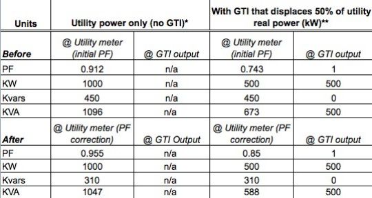 |
| Comparison of utility power factor with and without grid-tie inverter. *Fig.2 **Fig.3 |
Biography
Gerritt Lee received his BSEE degree from the U. of Hawaii and is a registered professional engineer employed by Hawaiian Electric Company; e-mail gerritt.lee@heco.com.