Energy converters for low wind speed
Dr. Razvan Panati Distributed Power Generation Drive Technologies Siemens Industry, Inc. Alpharetta, Ga.
New converter architectures let generators produce power in light breezes.

Hey, there is wind, but the windmills are not turning! What’s wrong with that picture?
This is a scenario wind turbine manufacturers and owners dread. If turbines are directly connected to the grid, they need a certain minimum wind speed to start producing energy. Otherwise they either consume energy or are stopped. Nobody likes that, but it is a quality of the directly connected induction generators which must turned at a speed above their synchronous speed to start delivering power to the grid.

Here is what happens: An induction generator connected to the grid will, in general, work as a motor. It absorbs power and runs at its nominal rotation frequency, slightly lower than 60 Hz. If something (in this case the wind) helps the generator speed up, the energy transfer slowly changes direction and, from a certain speed upwards, the electrical machine actually attempts to brake to keep its rotation frequency close to the grid’s 60 Hz, thus pushing the energy to the grid.
When the wind blows too hard, the blades of the turbine are pitched out to let more wind pass through them. This keeps the rotation speed nearly constant, at the 60 Hz mark. When the wind dies out, on the other hand, the blades are pitched in to capture as much wind as possible and maintain the generator speed above that of the grid frequency. At some point the generator reverts back to acting as a motor and the turbine must shutdown. Otherwise, its owner would have to pay for the energy consumed by the generator running in motoring mode.
The wind industry has long used this type of mechanical control of pitching (blade orientation) or yawing (entire turbine orientation). But more and more manufacturers think “direct grid connection” is not the most efficient way to capture wind energy.
One cannot extract power from induction generators below synchronous speeds simply by modifying the turbine. For that, one needs to modify the frequency and voltage supply to the generator terminals. And that requires an electronic frequency converter.
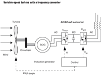
Variable-speed turbine operation

A bidirectional frequency converter lets any motion-based energy source (wind, water flow, steam pressure, wave intensity, tide level, etc.) generate power over a wide range of fluctuating conditions, thus rendering constant-speed operation unnecessary. It interfaces any generator, whether induction or permanent magnet, with the grid and enables power production at low speeds. It also protects the generator/grid at high wind speeds via automatic commutation of dc braking resistor banks.
The frequency conversion unit consists of a rotor-side converter and a grid-side converter. The rotor-side converts ac from the generator to dc. It feeds power to a capacitor that acts as a dc voltage source (commonly called a dc bus) for the grid-side converter. The grid-side, in turn, converts the dc to ac at the frequency of the grid.
For induction generators in turbines, the use of a frequency conversion unit is extremely attractive because it lets the turbine generate energy at much lower wind speeds or water flow rates than possible otherwise. This reduces the cut-in speed and thus boosts overall efficiencies for installations that often see lighter breezes or variable water flow, thus necessitating head control.
Conversely, the controller can run in field-weakening mode (reducing the strength of the generator magnetic field to let the armature rotate faster) in severe winds or in water flows that would push the generator above its synchronous speed.
Meanwhile, the controller would maintain a constant dc bus voltage while allowing production of controlled power. These functions let the system use a higher cut-off speed limit and let the turbine extend its power generation capacity close to its mechanical safety speed limits.
Under the above circumstances there is no need for pitch control to manage the turbine power output. Water systems can use the proper head at a given flow. However, the pitch may be cranked back to limit the rotation speed of the turbine in severe winds, thus letting the generator maintain its speed/power curve even in these conditions. Ultimately, blades are completely pitched-out to protect the turbine from extreme winds.

An example of a frequency converter for renewable energy applications of this sort is the M2G Energy Converter by Siemens. It contains two parts: a custom generator-interface cabinet (front-end) containing the turbine and generator controls, and a standard grid-interface cabinet (back-end).
To connect to grid, the energy stored temporarily on the dc-bus capacitive bank is converted to ac voltage by a so-called Active Line Module (or the line inverter). The unit is controlled by the same intelligent drive controller which, via a carefully defined switching pattern, produces a quasi-sinusoidal output voltage at the frequency defined in the parameter set. The voltage amplitude and frequency is constantly controlled in a closed-loop configuration using a voltage sensor supplied with the cabinet.
The converter uses an advanced control algorithm for generator control that is selectable between servo or vector mode to permit bidirectional control of the turbine. This means the generator can run, if needed, in motoring mode. In either the vector or servo mode, the active power output determined by the torque generating current component can independently be controlled and/or limited based on the power demand and generator rated parameters.
The back-end is designed to produce the functions required by the UL 1741 and IEEE 1547 standards for anti-islanding. Anti-islanding refers to how the conversion circuit must perform in the event of a power failure on the grid: It must turn off in a short period of time. This prevents it from continuing to feed power into small sections of the grid, known as “islands.” The problem with islands is that they present a risk to workers who may expect the area to be unpowered. Moreover, without a grid signal to synchronize to, the converter may put out power at a frequency that could drift away from that of the grid or, equally bad, sync up with other renewable energy converters feeding energy into the island. The standard for anti-islanding protection in the U.S. is UL 1741, harmonized with IEEE 1547.
The M2G front end allows a connection to one or more three-phase generators (induction or permanent magnet) and at the output produces a clean sinusoidal three-phase voltage, of user-selectable amplitude and perfectly synchronized with any grid type (weak or strong) in conformance to IEEE 1547 standards for grid interconnection harmonics. It also corrects and improves the grid power factor from lagging to leading and utilizes a separate cabinet for all turbine controls, including pitch or yaw, safety and start/stop operations.
The converter manages generator current (torque) to deliver the exact amount of power required by the instantaneous load, while ensuring the generator never exceeds its thermal specifications. The generator can run in vector-oriented (no encoder needed) or servo mode (with encoder) if need be, which permits independent control over the magnetizing current/field component and the torque-generating current component.
The system can operate on either 50 or 60 Hz line supplies with a simple parameter change in the controller. The M2G can let users select the amplitude of the three-phase output voltage in a range up to 480 V, so the inverter can connect to various grids.
The power factor facility allows for reactive power compensation. Many times the manufacturing equipment or HVAC motors/compressors of a plant or a building produce a large lagging power factor which utilities generally don’t like. The M2G Inverter can help compensate the lagging power factor by generating a user-adjustable power factor around unity in the interval 0.9 to -0.9. Two elements between the inverter and the utility make this possible: an active interface module and a basic line filter. These modules, along with specially designed control software, produce a controllable output power factor and a filtered, sinusoidal output voltage that exceeds U.S. requirements for harmonic distortion.
Resources
Siemens Industry, Inc., Alpharetta, Ga., www.usa.siemens.com/motioncontrol
© 2012 Penton Media Inc.