Beyond the hype of Hyperloop: An analysis of Elon Musk's proposed transit system
By Brian Dodson
August 22, 2013

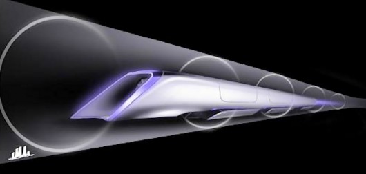
Design sketches of Elon Musk's proposed Hyperloop high-speed tube transport system
Now that the media kerfuffle surrounding Elon Musk's Hyperloop transit system proposal has settled down to a dull roar, it's a good time to step back and consider in detail some of the real innovations and difficult issues raised through analysis of the 57-page Hyperloop plan.
The shortest description of the Hyperloop is Musk's own bon mot: "It's a cross between a Concorde, a rail gun, and an air hockey table."
A slightly more complete description of the concept is that of an elevated, reduced-pressure tube that contains pressurized capsules driven within the tube by a number of linear electric motors. These capsules move with very little friction or drag owing to air bearings that ride on the inner surface of the tube, and a combination of active and passive means to reduce the negative effects of choked airflow on the transportation system.
In this article I am only considering the science and engineering aspects of the Hyperloop. While acknowledging that political issues may actually determine its fate, what concerns us here is whether or not it could work.
A Quick Overview
A reaction many people have to the Hyperloop is that there is nothing new here. While it's fair to say that all inventors are standing on the shoulders of giants to a certain degree, there are in fact very real innovations in Musk's proposal.
The Hyperloop has essentially no relationship with the old pneumatic tube transports beyond a certain similarity of appearance. There is, however, quite a bit of overlap with earlier proposals for reduced pressure or vacuum-tube transports. In particular, the early theoretical and experimental work of Robert Goddard, the inventor of the liquid fuel rocket, appears to have the greatest overlap with the Hyperloop.
Goddard's notes about reduced pressure transports sat in storage for over 30 years, only surfacing after his death in 1945. In US patent 2,511,979, he describes nearly every major feature of the Hyperloop save for the use of linear electric motors for propulsion (he preferred using reaction motors for propulsion), and using special apparatus to minimize the detrimental effects of choked airflow around the capsules. Goddard also described the use of air bearings, but of a very different sort than proposed for the Hyperloop. Many others, of course, have suggested the use of linear electric motors.
To sum up, it would appear that the main innovations in the Hyperloop proposal are the type of air bearings used to reduce friction forces on the moving capsules, and design elements that avoid the limitations encountered when the airflow around the capsules is choked. Let's take a closer look at these additions.
The Concorde part
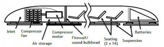
The Concorde portion of the Hyperloop is the capsule that rides within the tube. A passenger-only Hyperloop capsule holds 28 passengers in side-by-side pairs. The capsules are 1.35 m (4.4 ft) wide and 1.1 m (3.6 ft) tall.
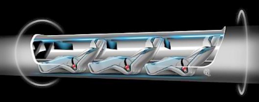
The riding position is rather like that of an airline seat with the back reclined and feet thrust forward. The amount of seating room will be similar to that of an economy airline seat where everyone has their seatback down.
Oddly, the length of the Hyperloop capsules is not directly addressed in the proposal. However, given the number of passengers, and the statement that the rotor on the capsule is 15 m (49 ft) in length, the total capsule length is probably in the neighborhood of 25-30 m (~80-100 ft) ... which interestingly equates to a scaled-down Concorde fuselage.
The most important innovations appearing in Musk's Hyperloop proposal have to do with reducing the drag and friction associated with a capsule moving through a tube. A long-standing approach to part of this problem is to reduce the pressure of the air in the tube. This reduces simple air drag and enables the capsule to move faster than through a tube at atmospheric pressure.
This isn't enough however. If the capsule fills too much of the cross-section of the tube, the air won't have time to flow around the capsule as it moves. In this condition, called choked flow, some of the air will back up in front of the capsule, and eventually the entire column of air in the Hyperloop tube is being pushed ahead of the capsule. When this happens, the friction between the air and the tube wall becomes enormous.
Choked flow begins when the pressure ahead of the capsule becomes about twice the pressure following the capsule. Given the Hyperloop dimensions and operating conditions, this starts at speeds around 500 mph (~800 km/h), and is associated with a dramatic increase in air drag.
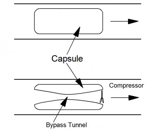
To avoid being limited to these speeds, Musk's team has introduced a new idea for reducing pressure in the tube. They propose installing an air compressor in the front of the capsule to pump the air which will not flow around the capsule and send it to a bypass nozzle at the rear of the capsule. This reduces the amount of air that must flow around the sides of the capsule, thereby enabling capsule speeds near Mach 1.
In the passenger-only Hyperloop capsule design, an air compressor mounted at the front of the capsule compresses about half a kilogram of air per second to a pressure 20 times larger than the initial pressure, in the process raising the temperature of the gas to about 585ºC (1085ºF). This will require an air compressor powered by a 325 kW (436 hp) electric motor.
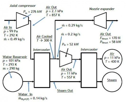
There does appear to be some inconsistency on the use of an air compressor in Musk's proposal. In the text on page 17, it appears to state that a portion of the compressed airflow is split off to be bypassed through the capsule before the remainder is cooled. However, in the drawing on page 18 (shown above), it appears that the bypassed air is split off after the entire output of the compressor is cooled.
It seems clear to me that the preferred situation would be that described in the text, as the cooling requirements of the capsule wind up being 60 percent smaller if the bypass air is not cooled within the capsule, especially as the amount of cooling required has been raised as an issue by some commentators. I will assume this arrangement below, but will also keep an open mind for ideas as to why the cooling of the bypassed air makes sense.
The bypassed air, at a mass flow rate of about 0.3 kg/s, is directed to a nozzle at the rear of the capsule, which also allows the bypassed air to supply additional driving thrust in the neighborhood of 150-200 N (35-45 pounds), or about half the thrust required to maintain a speed of 310 m/s (700 mph).
The remaining 0.2 kg/s of air output from the compressor is cooled to around room temperature mainly by converting water to steam and hot water in an intercooler. Once cooled, the air enters a second compressor, which increases the air pressure to 11 kPa, or about 7 N/square meter (1.6 psi). This doubly-compressed air is sent through a second intercooler that reduces the air temperature to about 125ºC (260ºF), from which it is directed to supply the air bearings.
The proposal suggests that about 0.14 kg/s of cooling water will be required to supply the intercoolers. This is a typical water flow rate for a racing intercooler mounted between a turbocharger and an engine to cool the air charge, thereby increasing the maximum power of the engine. The intercoolers for the Hyperloop capsules will have somewhat different engineering specifications, but suitable technologies exist in the market. It will only require adapting those technologies to this new operational regime.
For a one-way trip from end to end, about 400 kg (882 lb) of water must be available for cooling. This would fit within a square tank less than 0.75 m (2.5 ft) on a side, easily fitting in the Hyperloop capsule. The tank to contain the hot water and steam generated would be somewhat larger, but as the required cooling is only enough to convert one-third of the cooling water into steam, this problem may be solved by steam condensation once past the intercoolers. These tanks, along with the batteries powering the capsule systems, are configured as modules to be swapped out at the beginning of each trip through the Hyperloop.
In summary, these innovations reduce the operating pressure of the air inside the tube to about one-thousandth of atmospheric pressure, or about 100 Pa (0.015 psi). This reduces simple air drag to the point that only about 100 kW of motive power is required to overcome the drag at 940 km/h (700 mph). Operating a Hyperloop at reduced pressure is not only possible, but practical. A streamlined design is still required to minimize drag forces though, as the capsule shape diverts the air in the tube to pass around the sides.
The Rail Gun part
The rail gun aspect of the proposed Hyperloop is the set of linear electric motors that accelerate or decelerate the capsule at the appropriate times. The route chosen for the Hyperloop places capsule restrictions in the various parts of the route. The reason for this is because the lateral acceleration experienced by the passengers would become rather uncomfortable at about 0.5 g, and this lateral acceleration becomes greater at larger speeds and for smaller turn radii.
Musk's team has designed a route that allows three different capsule speeds. Near the ends, the velocity is limited to less than about 300 mph (480 km/h). In hilly regions where the Hyperloop roughly follows Interstate highways, the capsule speed can be increased to 555 mph (890 km/h). Finally, the longest segment follows I-5 up the center of the state requiring only the most gradual of turns, and can allow capsule speeds of 760 mph (1,220 km/h.) Remember that the fastest speeds are only accessible because of the air bypass compressor in each capsule.
The various speed limits require that the Hyperloop operators be able to control the speed of the capsules through a number of accelerations and decelerations. This is the role of the linear induction motors. The hardest job is the acceleration for the I-5 portion of the route, when the speed must be increased from 300 mph to 760 mph at an acceleration of 1 g. This is the accelerator that will be described below, but others would be required in other locations along the route.
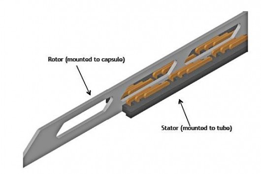
The linear induction motors are extremely simple from a mechanical point of view. In the Hyperloop design the only part of the motor on the capsule is the rotor. The rotor is a simple piece of aluminum 15 m (49 ft) in length, 0.45 m (1.5 ft) tall, and 5 cm (2 in) in width. The induced current flows mainly near the rotor surface owing to skin effect, so the interior of the rotor can be hollow to save weight.
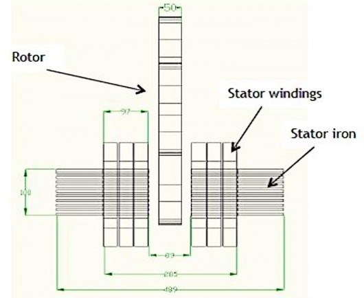
The rotor rides between magnetic elements of a stator, which are permanently affixed to the Hyperloop tubes in the locations required, and extend the full length over which acceleration or deceleration is to be carried out. For example, the stator of the motor that accelerates the capsules to 760 mph is a full 2.5 miles in length, and weighs over 3,000 tons (2,722 tonnes), so it is happy to remain stationary. Each linear induction motor can use up to 65 MW during peak operation.
By altering the control and power circuit controls, the linear motors, instead of adding motive power to accelerate the moving capsules, can function in reverse, drawing electrical power from the kinetic energy of a capsule to slow it down. Rather like a regenerative brake on a car, the linear motors store this power for later use. Such regenerative systems can be as much as 85 percent efficient, so that most of the energy required to power a capsule through the Hyperloop can be drawn from power saved from the slowing of the previous capsule's journey.
Musk's proposal also outlines a solar power system to power the Hyperloop. Based on covering the upper surface of the twin Hyperloop tubes with solar cells, this solar array is projected to supply about 57 MW of electrical power on average, while the Hyperloop is expected to consume an average of only about 21 MW. This being solar power, it is clear that power must be shuttled back and forth between the Hyperloop and other utilities, but that is a routine process. In addition, a battery array would be required at each stator station, as the peak powers required locally are several times the average supply. The batteries can also be used in a regenerative braking mode to store the kinetic energy of a capsule. The excess power can be sold to provide around US$25M per year, which will help with Hyperloop operational costs.
Overall, the rail gun part of the Hyperloop is a fairly standard (if gigantic) piece of engineering.
The Air Hockey Table part
The third of Musk's triad is the air bearings upon which the capsules will ride with a minimum of friction. The air bearing best known to many of us is the little puck that slides around on an air hockey table. Pressurized air comes out of a grid of small holes on the hockey table surface, and the puck is lifted by this air. Air bearings provide nearly frictionless motion.
Most modern proposals for vacuum and reduced pressure trains, as well as open high-speed trains, call for suspending the moving vehicle using magnetic levitation. While this is currently the trendy approach, it is actually quite expensive and difficult to control.
By comparison, air bearings have natural stability, low friction, and long lifetime. Air bearings are also a natural fit to the Hyperloop, in which the capsules already contain a compressor system required to reduce air drag at high speeds. Bleeding off some of the compressed air from the bypass system and use it to feed the air bearings seems a natural synergism.
A Hyperloop capsule is supported by a set of 28 air cushion skis, each of which is 4.9 ft (1.5 m) in length, 3 ft (0.9 m) in width, and is curved to match the inner surface of the Hyperloop tubes. The thickness of the air cushion is between 0.5 and 1.5 mm (20 - 50 mils). The total pressurized area available to lift and support the capsule is about 410 sq ft (38 sq m). As an air bearing is rather stiff in reaction to external forces, each of the skis is mounted to the capsule via a second suspension system.
The pressurized area is crosscut with a number of channels that distribute the 11 kPa air from the second intercooler to feed the air cushion at a mass rate of 0.2 kg/s. This doesn't seem like much, but over a 45 minute transit, over 500 kg (1100 lb) of air must be supplied to the air bearings. Carrying air on each capsule flight does not seem a practical procedure, so diverting some of the bypassed air to this purpose allows the bearing system to function effectively.
When the capsule is moving rapidly, there is an additional aerodynamic source of air for the air cushions. The front edge of each ski is set higher than the rear by about 1.3 mm. When the capsule is moving rapidly, viscous interactions trap an air cushion in the converging gap between the ski and the tube surface. However, this aerodynamic supply of air is insufficient at any capsule speed for which the Hyperloop is designed – it simply augments the air from the compressor.
The interaction of the air cushion with the tube wall produces a small amount of viscous drag on the capsule. Estimates, however, show that the drag at 760 mph (1220 km/h) is about 31 pounds, or 140 Newtons of force. This is less than half of the total drag estimated at this capsule speed.
Hyperloop Route
The proposed route for the Hyperloop runs from North Valley, CA to the San Francisco end of the Bay Bridge. It ignores the short urban runs, probably because the selection of a route for these runs is mainly a detailed political and economic process.
The route is split into a series of segments. Roughly a particular capsule speed is associated with each of the segments, and that capsule speed is set by the minimum turn radius encountered on that segment.
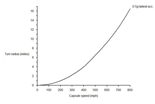
As discussed, turn radius enters into route selection because strong lateral accelerations (say, above 0.5g) are unpleasant to a passenger. When you follow a curved path, your body wants to travel in a straight line, but it is stuck inside a capsule that is following a curve. This effect, called centripetal acceleration, pushes the passengers sideways. The strength of the effect increases with the square of the velocity and decreases with the turn radius, which results in a simple relationship between turn radius and capsule velocity.
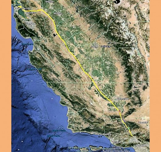
The first segment, stretching from North Valley to Castaic, has a number of sharp turns, limiting the speed to about 300 mph (480 km/h) on that segment. The segment from Castaic to a few miles north of Lebec cuts through some sharp turns along tunnels, and as a result is compatible with capsule speeds of 550 mph (890 km/h).
Form Lebec to the divergence of I-5 and I-580, I-5 is extraordinarily straight, allowing the capsule to travel this segment at 760 mph (1220 km/h). The final segment runs along I-580 with some tunnel bypasses near Dublin. The speed on this segment starts at 550 mph, and slows to 300 mph as the capsule enters areas with sharper turns.
A property of the Hyperloop that is not obvious at first sight is how few stators are required for operation. If a capsule is given a speed of 760 mph at the start of the I-5 segment, it can coast to the other end (some 230 miles or 335 km distant), and arrive moving at a speed of about 730 mph (1,170 km/h). This is the direct result of the extraordinarily low drag and friction of the proposed Hyperloop. In other words, most of a trip is spent coasting.
Coda
"When a distinguished but elderly scientist states that something is possible, he is almost certainly right. When he states that something is impossible, he is very probably wrong". Clarke's First Law
I need to echo the common concern that Musk's estimates for the construction costs seem low. For example, the cost of a Hyperloop capsule is projected to be about 1.35 million US dollars. If a comparison is made with light jets having fuselages of similar dimensions to a Hyperloop capsule, it turns out that such jets cost about 10 times Musk's estimated amount. Clearly, a Hyperloop capsule does not have to survive the stress levels that a jet might see, and capsules don't have wings and tail assemblies (not to mention turbofan engines), but still the numbers still seem too low.
More generally, it appears to me that most of the objections presented concerning the Hyperloop are either based on incorrect engineering analysis, or simple prejudice claimed as a truth. There are also a number of pronouncements to which Clarke's First Law would apply.
The real issue is if Musk will take on the project of building a demonstration "Hypoloop." That is the next step, and most of the usual avenues for project development won't swing their doors wide for such a project. Fortunately, Musk is a billionaire, and has friends. We may find out if the proposed Hyperloop is practical sooner than one might expect.
Source: Hyperloop Alpha / Tesla Motors
Copyright © gizmag 2003 - 2013 To subscribe or visit go to: http://www.gizmag.com