The best of both worlds: combining batteries and supercaps
Hybrid capacitors deliver the power density and energy that today’s electronic systems need.
By NORBERT PIEPER,
Senior VP Sales Business Development,
Vishay Intertechnology,
www.vishay.com
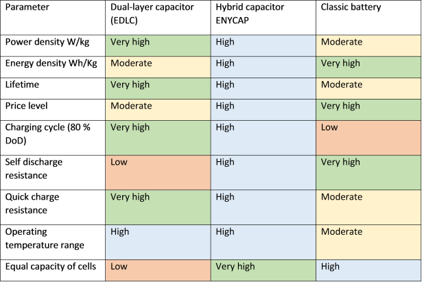
From home automation to industrial robots, our networked world demands that electronic systems offer constant availability, resulting in the need for permanent — often network-independent — energy supplies. Rechargeable batteries are practical and reliable for these systems until they reach the end of their working life, when they must be replaced or thrown away. Classic solid electrolyte capacitors provide a more environmentally friendly and cost-neutral alternative, but soon reach their limit with output requirements exceeding 100 mW. Supercap dual-layer capacitors offer high power density and long working life, but low dielectric strength. Electronic systems require a compromise between these technologies, solutions that combine the advantages of classic batteries and dual-layer capacitors without the limitations. Refer to the Table for comparison among the dual-layer capacitor, the typical battery, and the Hybrid ENYCAP capacitor.
Table: Basic comparison of the capacitor and battery systems.
The physical single cells of ENYCAP 196HVC devices have a
nominal maximum voltage of 1.4 V and can be interconnected in
series without special balancing measures, thus achieving higher
nominal voltage. Currently, voltages of 8.4 V and capacitance
values between 4 F and 90 F can be obtained.
Due to their low constructional height (<2.5 mm) and easy
combination options, such cells allow good adaptation to
existing construction space, which is often very restricted and
is sometimes located in the “third” dimension outside the PCB
level.
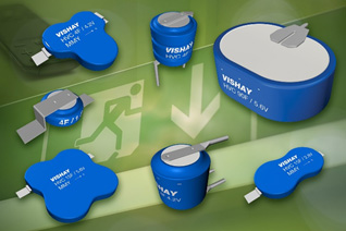
Fig. 1: ENYCAP structural form variations.
Hybrid systems can reach very high energy densities of >13
Ws/g (>3.6 Wh/kg) and are, therefore, a viable alternative to
the classic battery. Furthermore, these energy storage
capacitors are characterized by very low stray current and
self-discharge.
The balance of power is demonstrated in Fig. 2, which
shows the optimum classification of ENYCAP storage capacitors
according to today’s state-of-the-art technology.
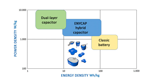
Fig. 2: Balance of power chart for capacitors, batteries and hybrid capacitors.
As already implied in the examples above, specific parameters must be tuned to the respective application to select the correct component:
- Backup energy and time interval. Here, the periods between very deep discharging and, in particular, the time up until the first backup are particularly critical.
- Specific peak power and peak current requirements.
- Output voltage level for the backup solution; in particular, the minimum voltage level.
- Input voltage range that is available for loading the energy storage device; in particular, the maximum range.
- Impedance of the primary energy source. For systems with low ESR, extremely high charge current spikes can occur.
- Protection against complete discharging, short circuits, reverse polarity, overvoltage, and excess temperature.
- Charging status control of the energy storage device and data-bus-capable signals for advanced power management systems.
- Cost of the entire system.
The parameters above are only a selection of the most important design parameters. To make the complexity clear, the following illustrations (see Figs. 3 and 4) of the principle will show the basic diagrams of charging current, discharge current, and voltage curve over time. The difference in the behavior between hybrid energy storage and classic supercaps can clearly be seen.
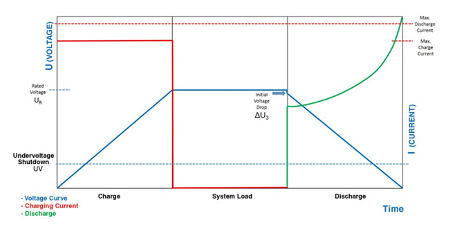
Fig. 3: Dual-layer capacitor as a backup source.
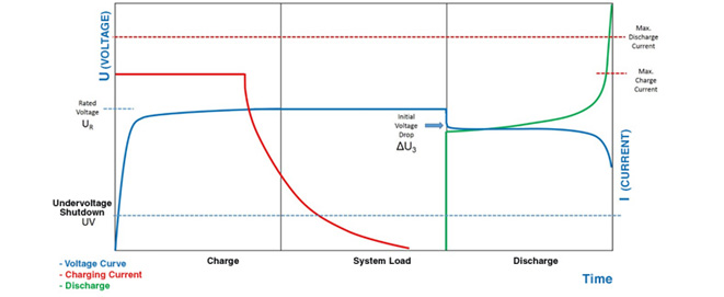
Fig. 4: ENYCAP as a backup source.
The good charging and, where applicable, fast charging
behavior of dual-layer capacitors can be observed from the
voltage plot. It can be seen that precautionary measures must be
taken against extreme current charge peaks due to the low ESR.
Furthermore, with constant backup power, the linear drop of the
discharge voltage results in a disproportionate increase of the
discharge current and constant back-regulation of the dc/dc
converter as well as high current peaks. In some cases, higher
ripple currents at the capacitor have to be taken into account.
The hybrid dual-layer capacitor is characterized by its more
gentle charging behavior due to its higher series resistance and
optimized construction. The nominal voltage on the capacitor is
reached at a very early stage, allowing simple operation of
wake-up switching and low-power sensor applications. The
virtually constant voltage curve and resulting constant
discharge current in the operating range are also advantageous.
The control electronics can certainly be simplified as opposed
to dual-layer capacitors. The relatively high initial voltage
drop is a disadvantage.
To lighten the burden on the user caused by the differences in
these systems, it’s important to provide the customer with
complex solutions and design references that integrate the basic
functions, such as charging and discharging (see Fig. 5), and
the required protective circuits. The manufacturers of the
storage elements and charge controllers must collaborate in
advance, if possible, to adapt the specific conditions to the
system.
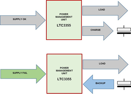
Fig. 5: Charging and backup block diagram using an LTC3355.
An example is a reference design that integrates an emergency
current solution with a charge controller circuit and a backup
converter, including the necessary current measurement sensors
to evaluate the function as well as all protective functions.
Moreover, this system can be operated using ENYCAP, dual-layer
capacitors, classic capacitors, and batteries, and realizes
automatic switching between primary supply plus charge function
and energy source backup. For this purpose, charging voltage
(1.3 V to 3.2 V), charging current (35 mA to 600 mA),
discharging voltage (>1 V), and discharging current restriction
(100 mA to 5 A) can be varied in several ranges and can easily
be adapted to the customer’s circumstances. The charging process
can use either constant current or constant voltage regulators.
The provided buck converter transforms to the programmed supply
voltage for the load and charges the backup energy storage
device. In case of an interruption of the supply voltage, the
boost converter, which is also integrated, maintains the output
voltage on the load without any interruption until the secondary
energy source is exhausted. On top of this, a simple load switch
on the output side switches off the load if the minimum
capacitor voltage of about 1 V is undercut. This avoids complete
discharging and constant linear operation of the connected
regulators.
The LTC3355 IC performs all of the functions that are required,
for example, within an intelligent power management system for a
server or an IPC. Monitoring the voltages VIN, VOUT, and VCAP,
basic information (open-drain signal outputs) regarding the load
status of the energy source (CPGOOD) and the automatic
switchover of the supply to the backup energy storage device
(PFOB), as well as load regulation, are available. The regulator
processes input voltages of 4.0 V to 20 V and supplies a
regulated output voltage of 3.0 V to 5.0 V. The component has
integrated overheating protection, which is also used to monitor
the maximum permissible current.
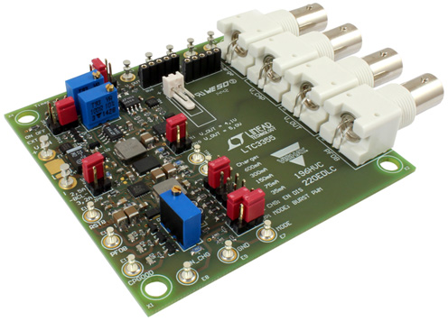
Fig. 6: Evaluation design kit (MAL219699001E3).
ENYCAP energy storage capacitors have a higher power density
than a battery and higher energy density than classic electric
dual-layer capacitors (EDLC). Therefore, faster charging and
discharging times are possible than those for a battery. We
suggest impulse charging for applications such as backup
systems. The idea behind this is that the ENYCAP is initially
charged up to the maximum of its energy storage capacity and
then the charge status is maintained in a trickle mode by
individual electrical impulses. This compensates for
self-discharge and the capacitor is kept under ideal operating
conditions. If charging were to take place constantly and only
be switched off when the supply is interrupted, the working life
of the product would be reduced dramatically. The maximum charge
voltage should be set somewhere between 2% and 3% higher than
the specified nominal voltage (rated voltage). This compensates
for the voltage drops at the product’s internal resistor. Cell
voltage is always lower than charge voltage. It is very
important that the energy storage capacitors are loaded up to
full nominal voltage. Higher voltages should not be used. It
must be taken into account that the product of charge
current*charge time is equal to the maximum charge. Only then is
the maximum degree of effectiveness and the highest possible
energy storage achieved.
ENYCAP 196 HVC series capacitors are specified for normal
storage conditions of –40° to +85°C. However, after one year of
storage, the parts should be powered and charged. Self-discharge
is low. The permanent charge voltage of a fully charged
capacitor must be limited to ≤20 µA; otherwise, the product will
age early. If higher current flows, it must be ensured that the
ENYCAP 196 HVC is removed from the circuit. Complete
self-discharge must also be avoided. Most of the energy can be
removed from the single cell between 1 V and 1.4 V. Cell
voltages under 1 V result in deep discharge. As a result, low
discharge currents can already have negative influence on the
product’s properties.
When selecting the other components, great care was made to
ensure low dc-circuit loss, low temperature factor, and high
efficiency inductances to make the available energy as fully
usable as possible. Also, input protection circuitry with TVS
diodes was implemented to avoid overvoltage events of the
complete circuit.
Learn more about Vishay Intertechnology